

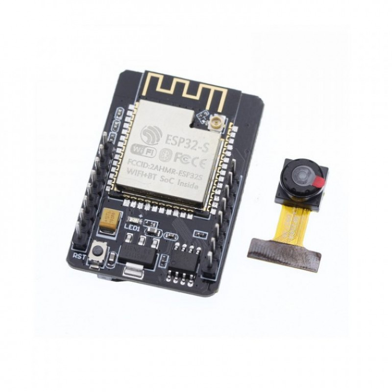
ESP32 CAM WiFi Module Bluetooth With OV2640 Camera Module 2MP COM52 ,R12
DescriptionThe ESP32 CAM WiFi Module Bluetooth with OV2640 Camera Module 2MP For Face Recognization has a very competitive small-size camera module that can operate independently as a minimum system with a footprint of only 40 x 27 mm; a deep sleep current of up to 6mA and is widely used in various IoT applications.ESP integrates WiFi, traditional Bluetooth, and BLE Beacon, with 2 high-performance 32-bit LX6 CPUs, 7-stage pipeline architecture. It has the main frequency adjustment range of 80MHz to 240MHz, on-chip sensor, Hall sensor, temperature sensor, etc.SpecificationsIO Port: 9Power Supply: 5V 2AWiFi: 820.11 b/g/n/e/iSPI Flash: Default 32MbitSpectrum Range: 2412-2484MHZSerial Port Rate: Default 115200 bpsRAM: Internal 520KB External 4M PSRAMAntenna Form: Onboard PCB antenna, gain 2dBiBluetooth: Bluetooth 4.3 BR/EDR and BLE standardImage Output Format: JPEG (Only OV2640 support), BMP, GRAYSCALEFeaturesSupport TF card.(Max 4G)Support image WiFi upload.Support multiple sleep modes.Embedded Lwip and FreeRTOS.Support secondary development.Support STA/AP/STA AP working mode.Built-in 520 KB SRAM, external 4M PSRAM.Support OV2640 and OV7670 cameras, built-in flash.Supports interfaces such as UART/SPI/I2C/PWM/ADC/DAC.Support Smart Config/AirKiss one-click distribution network.Transmit Power820.11b: 17±2dBm (@11Mbps);820.11g: 14±2dBm (@54Mbps);820.11n: 13±2dBm (@MCS7)Safety: WPA/WPA2/WPA2-Enterprise/WPSApplicationSmart agricultureWireless monitoringHome smart device mapQR wireless identificationGetting started with the ESP32 CAM WiFi Module Bluetooth with OV2640 Camera Module 2MPThis article is a quick getting started guide for the ESP32-CAM board. We’ll show you how to setup a video streaming web server with face recognition and detection in less than 5 minutes with Arduino IDE.Hardware requiredESP32-CAM with OV2640CP2102 Converter USB to Serial UART or ESP32-CAM-MB Micro USB ProgrammerFemale-to-female jumper wiresThe ESP32-CAM doesn’t come with a USB connector, so you need a CP2102 Converter USB to Serial UART to upload code through the U0R and U0T pins (serial pins).Connecting the Hardware Using USB to Serial UART adapterPlug your USB cable to FTDI AdapterConnecting the Hardware Using ESP32-CAM Programming Adapter BoardPlug your usb to the ESP32-CAM-MB Micro USB Programmer.Setting up the library and BoardAdding ESP32 platform to Arduino IDEOpen the Preferences window from the Arduino IDE. Go to File -> Preferences.Paste the following line into the Additional Boards Manager URLs field: https://dl.espressif.com/dl/package_esp32_index.jsonIf you have entries in this field already then add the new line before them but separate them with a comma.Go to Tools -> Board -> Board Manager…Type ESP32, point with mouse cursor on record line found (ESP32 by …) and click on Install button to install the new hardware libraries.When installation done, close and open your Arduino IDE again. You will be able to find all the ESP32 boards in the Arduino IDE’s board selector.Upload the sample sketchIn your Arduino IDE, go to File > Examples > ESP32 > Camera and open the CameraWebServer example.The following code should load.Before uploading the code, you need to insert your network credentials in the following variables:const char* ssid = "REPLACE_WITH_YOUR_SSID"; const char* password = "REPLACE_WITH_YOUR_PASSWORD";Getting the IP addressAfter uploading the code, disconnect GPIO 0 from GND. Open the Serial Monitor at a baud rate of 115200. Press the ESP32-CAM on-board Reset button. The ESP32 IP address should be printed in the Serial Monitor.RESULTSNow, you can access your camera streaming server on your local network. Open a browser and type the ESP32-CAM IP address. Press the Start Streaming button to start video streaming. You also have the option to take photos by clicking the Get Still button. Unfortunately, this example doesn’t save the photos, but you can modify it to use the on board microSD Card to store the captured photos. There are also several camera settings that you can play with to adjust the image settings.How to program ESP-32 cam using Arduino UNO boardIn this article, I am going to describe how to program ESP32 cam module using arduino IDE & without FDTI & any other USB to ttl converter.This low price development board has onboard 5volt to 3.3-volt voltage regulator chip, an ESP32 chip with Bluetooth(BLE), wifi, GPIO pins, 2MP camera & a big sized SMD led but unfortunately this cheap board has not any onboard programmer chip like other nodemcu board. Usually, we have to program it using FDTI or USB to TTL converter. IF you don’t have any USB to TTL converter & have an Arduino UNO then no need to waste money to buy this TTL converter.You need to program in this methodESP32 camArduino UNO boardJumper wireArduino IDE softwareConnection ESP32 cam to Arduino UNOConnect Arduino 5volt to esp 32 cam 5 volt.Arduino GND to GNDArduino RX to Cam board RX & TX to TXArduino reset pin to GNDESP 32cam D0 to GndMake sure the cam board DO is connected to gnd. It will enable esp 32 flash mode otherwise you can’t program it. after compleat, the programming remove D0 to gndNow open Arduino IDE on your PC, go to File > Preferences >Now paste below link in the board manager URLhttps://dl.espressif.com/dl/package_esp32_index.jsonNow go to Tools > Board > Board manager > & search for ESP 32You can see esp 32 board Download & install the latest version package After complete, the installation go to Tools > Select port where arduino UNO is connectedNow go to board > select board > ESP32 ” Wrover Module”Flash Mode > QIOFlash Frequency > 40MHZPartition Scheme > Huge App (3mb No OTA)Upload speed > 115200Programmer > AVR ISPNow it is ready for uploading sketchYou can test it Go to File > Example > ESP32 > Camera > Camera web server and upload the sample sketchPackage includes: 1pc × ESP32 CAM WiFi ModulePackage
Share on: