

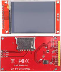
2.8 inch 240×320 TFT LCD module Display touch panel SD card COM34
DescriptionThis is TFT touchscreen LCD display which is used to interface with arduino and can show image.Specification:– LCD size: 2.8 inches – Driver IC: ILI9341 – Resolution: 320*240 (RGB) – Color depth: 16 bits (65K colors) – Operating voltage: 3.3V or 5V – Backlight voltage: 2.8~3.3V, high bright 4LED – Power Dissipation: 60~70(mA) – Touch screen type: resistive, glass touch screen – Interface mode: 16-bit (default)/8-bit configurable – Module size: 51mm*82.6mm – Display area size: 57.6mm*47.2mmSetup GuideHardware RequirementsMicrocontroller: ESP32Display:2.8 inch 240×320 TFT LCD moduleTouch Controller: Built-in SPI Touch (usually XPT2046)Software: Arduino IDELibrary: TFT_eSPI by Bodmer1. Wiring ConnectionsBecause the display and the touch controller both use the SPI interface, they share the main SPI data pins (MOSI, MISO, SCK), but they require unique Chip Select (CS) pins so the ESP32 can talk to them individually.Display Pin (14-Pin)DescriptionESP32 PinNotes1. VCCPower (3.3V)3V3Do NOT connect to 5V.2. GNDGroundGND 3. CSTFT Chip SelectGPIO 15 4. RESETTFT ResetGPIO 4 5. DC / RSData/CommandGPIO 2 6. SDI / SDATFT MOSIGPIO 23Shared SPI Data In7. SCK / SCLTFT ClockGPIO 18Shared SPI Clock8. LED / BLKBacklight3V3Connect to 3.3V to keep the screen fully lit.9. SDO / MISOTFT MISO(Not connected)ST7789 usually doesn’t need MISO for graphics.10. T_CLKTouch ClockGPIO 18Shared SPI Clock11. T_CSTouch Chip SelectGPIO 21Must be unique to the touch controller.12. T_DINTouch MOSIGPIO 23Shared SPI Data In13. T_DOTouch MISOGPIO 19ESP32 SPI Data Out (Critical for Touch)14. T_IRQTouch Interrupt(Not connected)Not strictly required by TFT_eSPI.2. Library ConfigurationThe TFT_eSPI library must be configured to know which driver to use and where the pins are connected.Locate your Arduino libraries folder (usually Documents/Arduino/libraries/TFT_eSPI).Open the User_Setup.h file.Delete its contents and replace it with this clean, optimized configuration:#define USER_SETUP_INFO "ST7789_SPI_Touch" // 1. Display Driver #define ST7789_DRIVER // 2. Display Resolution #define TFT_WIDTH 240 #define TFT_HEIGHT 320 // 3. Hardware SPI Pins #define TFT_MISO 19 #define TFT_MOSI 23 #define TFT_SCLK 18 #define TFT_CS 15 #define TFT_DC 2 #define TFT_RST 4 // 4. Touch Pin #define TOUCH_CS 21 // 5. Fonts #define LOAD_GLCD #define LOAD_FONT2 #define LOAD_FONT4 #define LOAD_FONT6 #define LOAD_FONT7 #define LOAD_FONT8 #define LOAD_GFXFF #define SMOOTH_FONT // 6. SPI Frequencies #define SPI_FREQUENCY 27000000 #define SPI_READ_FREQUENCY 20000000 #define SPI_TOUCH_FREQUENCY 25000003. Touchscreen CalibrationTouchscreens are physically misaligned from the pixel grid out of the box. You must generate calibration data once to fix this.Upload the following calibration sketch to the ESP32.Open the Serial Monitor at 115200 baud.Use a stylus or pen cap to touch the arrows as they appear in the corners of the screen.When finished, copy the uint16_t calData[5] = { … }; line generated in the Serial Monitor.Calibration Sketch:#include <SPI.h> #include <TFT_eSPI.h> TFT_eSPI tft = TFT_eSPI(); void setup() { Serial.begin(115200); tft.init(); tft.setRotation(1); // 1 = Landscape tft.fillScreen(TFT_BLACK); tft.setTextColor(TFT_WHITE, TFT_BLACK); tft.setTextSize(1); tft.setCursor(20, 20); tft.println("Touch the corners as indicated"); uint16_t calData[5]; // Run the calibration routine tft.calibrateTouch(calData, TFT_WHITE, TFT_BLACK, 15); // Print the results to the Serial Monitor Serial.println("\n\n--- PASTE THIS INTO YOUR DRAWING SKETCH ---"); Serial.print("uint16_t calData[5] = { "); for (uint8_t i = 0; i < 5; i ) { Serial.print(calData[i]); if (i < 4) Serial.print(", "); } Serial.println(" };"); Serial.println("-------------------------------------------"); tft.fillScreen(TFT_GREEN); tft.setTextColor(TFT_BLACK, TFT_GREEN); tft.setTextSize(2); tft.setCursor(10, 50); tft.println("Calibration Complete!"); tft.println("Check Serial Monitor."); } void loop() {} 4. Final Testing / Drawing SketchThis sketch acts as a digital drawing pad. It verifies that graphics are rendering correctly and that the touch coordinates are mapped perfectly to the display pixels.Instructions: Replace the calData array in the setup() function with the numbers you generated in Step 3.C #include <SPI.h> #include <TFT_eSPI.h> TFT_eSPI tft = TFT_eSPI(); void setup() { Serial.begin(115200); tft.init(); tft.setRotation(1); // Must match the orientation used during calibration tft.fillScreen(TFT_BLACK); // ---> REPLACE THIS LINE WITH YOUR CALIBRATION DATA <--- uint16_t calData[5] = { 275, 3620, 264, 3532, 1 }; tft.setTouch(calData); tft.setTextColor(TFT_WHITE, TFT_BLACK); tft.setTextSize(2); tft.setCursor(10, 10); tft.println("Touch to draw!"); } void loop() { uint16_t x = 0, y = 0; // Check if the screen is being touched bool pressed = tft.getTouch(&x, &y); if (pressed) { // Draw a red dot where the touch was detected tft.fillCircle(x, y, 5, TFT_RED); // Print coordinates to Serial Monitor for debugging Serial.print("X: "); Serial.print(x); Serial.print(" | Y: "); Serial.println(y); // Hidden feature: Touch the top left corner to clear the screen if (x < 50 && y < 50) { tft.fillScreen(TFT_BLACK); tft.setCursor(10, 10); tft.println("Screen Cleared!"); delay(500); // Prevent rapid triggering } } }
Share on: