

7-Segment Display – CA-Red BX7 ,R15
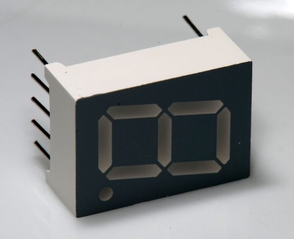
DescriptionBefore the era of OLED screens and LCD panels, the 7-segment display was the undisputed king of numerical output, and it remains a staple in hardware design today due to its high visibility and extreme reliability.Whether you are designing a rugged, high-contrast diagnostic dashboard for electric motorcycle maintenance, or teaching students how to map binary outputs during the Electronics Bootcamp, this Common Anode 7-Segment Display is an essential educational and prototyping tool.Understanding Common AnodeA 7-segment display is simply a package of eight individual LEDs (seven for the number segments A-G, and one for the decimal point). In a Common Anode display, the positive voltage pins (Anodes) of all eight LEDs are tied together internally to a single common pin.To light up a specific segment, you connect the common pin to your power supply (like the 3.3V or 5V rail), and apply a negative voltage (Ground) to the corresponding segment pin. In code, this means setting your microcontroller’s digital pin to LOW will turn the LED ON, and setting it to HIGH will turn it OFF. This inverted logic is incredibly common in industrial electronics and is a vital concept for beginners to master.The Golden Rule: Always Use Resistors!Just like any standard LED, you cannot connect the segment pins directly to Ground without protection. Doing so will draw too much current and instantly burn out the internal LEDs. You must place a current-limiting resistor (typically 220Ω or 330Ω) in series with each individual segment pin you plan to use.Visual Clarity & Form FactorAs seen, the stark grey face with white diffused segments ensures the lit LEDs stand out brilliantly, even in bright workshop environments. The standard 2.54mm (0.1″) pin spacing is perfectly optimized to bridge the center gap on any standard prototyping breadboard.Key Features:High Contrast: Diffused white segments on a grey background eliminate glare and make digits readable from a distance.Breadboard Ready: 10-pin DIP layout fits universally into breadboards, perfboards, and standard IC sockets.Decimal Point (DP): Includes a right-hand decimal point, making it perfect for displaying precise sensor data like firmware versions or battery voltages.Technical Specifications:Digit Count: 1 DigitPolarity: Common AnodeEmitting Color: RedForward Voltage (VF): ~1.8V to 2.2V per segmentContinuous Forward Current (IF): ~20mA per segment (Recommended 10mA – 15mA for longevity)Number of Pins: 10 (2 Common Anode pins, 8 Segment pins)Ideal Applications:Basic digital clocks, stopwatches, and tally countersHigh-visibility sensor readouts (voltage, temperature, speed)Microcontroller sink-current training and logic design labsInterfacing with active-low decoder ICs like the 74LS47
Share on: