

I2C LCD Controller Module for 1602 or 2004 DISP52,R11
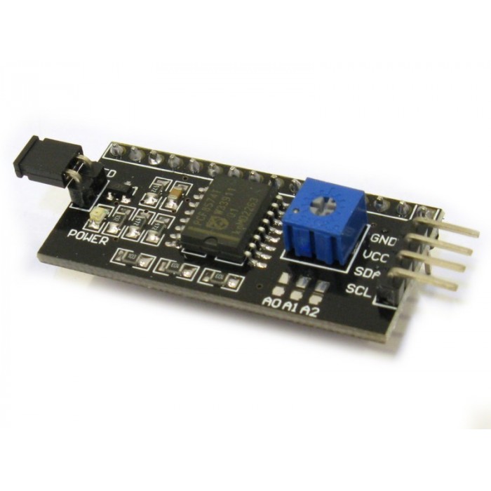
DescriptionWhen building embedded electronics systems—whether you are working on a custom diagnostic panel for electric motorcycle battery arrays or developing IoT tracking nodes—pins are premium real estate. A standard character LCD natively demands massive parallel wiring. This I2C LCD Backpack Module permanently resolves that issue, converting complex 16-pin parallel interfaces into an ultra-clean 2-wire setup.Whether you are designing compact sensor dashboards for immediate workshop deployment or preparing foundational hardware kits for the Electronics Bootcamp, this adapter is a mandatory tool for clean, efficient circuit routing.How the I/O Expansion WorksThe heart of this module is the PCF8574T surface-mount integrated circuit. This chip operates as a remote 8-bit I/O expander. When your microcontroller sends a highly compressed command over the standard I2C bus (using only the Serial Data line SDA and Serial Clock line SCL), the PCF8574T catches the transmission and unrolls it into the 8 parallel bits required by the screen’s HD44780 controller.Integrated Hardware ControlThe module eliminates the need to add external support components to your prototyping board:Contrast Adjustment: The blue multi-turn potentiometer allows you to dial in the perfect contrast with a small screwdriver, making your text stand out crisp and dark against the backlight.Backlight Control Jumper: The black 2-pin jumper header on the left edge provides a physical shortcut. Leave the plastic shunt on to keep the backlight permanently energized, or remove it to break the circuit. Alternatively, you can remove the shunt and run a wire from the inner pin to a PWM-capable pin on your microcontroller to dynamically control the screen brightness via code.Configuring Multiple Displays (Address Pads)By default, this module ships with a hardcoded I2C address of 0x27 (or 0x3F depending on the chip batch). However, if your project requires multiple screens at once, look closely at the board’s surface for three pairs of open pads labeled A0, A1, and A2. By bridging these pads together with a drop of solder, you change the binary addressing of the chip. This allows you to connect up to 8 completely unique LCD screens to the exact same two I2C wires without a single data collision.Key Features:Drastic Pin Reduction: Frees up your microcontroller’s digital pins for critical tasks like hardware interrupts, motor encoders, or cellular AT command tracking.Direct Form Factor: The male header pins are spaced at standard 2.54mm intervals, aligning perfectly with the top row of pins on standard 1602 and 2004 character displays for easy sandwich-style soldering.Massive Library Support: Supported natively by standard community libraries, such as LiquidCrystal_I2C.h, making code integration simple.Technical Specifications:Interface Protocol: I2C / IICCore Chip: PCF8574T (or PCF8574AT variant)Default I2C Address: 0x27 (for T-series) or 0x3F (for AT-series)Operating Voltage: 5V DCSupported Displays: 16×2 LCD, 20×4 LCD, and similar HD44780-driven character modulesDimensions: ~41.5mm x 19mm x 15mmIdeal Applications:Simplifying user interfaces for automated machinery and 3D printersStreamlining complex multi-sensor environmental telemetry dashboardsEliminating tangled wiring webs on student educational breadboardsBuilding dense, space-restricted control panels for industrial enclosuresGetting started with the I2C LCD Controller Module for 1602 or 2004In this tutorial, you will see how to connect i2c LCD display (Liquid Crystal Display) to Arduino using the i2c module. Before starting this article we will see what is i2c. I2C (I-square-C i.e IIC) means inter-integrated communication protocol. This is usually used to communicate between one master and multiple slaves. One of the best things about using I2C is we can reduce the connections (wiring). If you use normal LCD display, you need a total number of connections are 12. If you use I2C LCD display, you need only just 4 connection. By seeing the example you may know the advantage of I2C protocol. I2C protocol is also known as 2 line protocol. Hardware requiredArduino UnoI2C LCD displayLCD 16×2 OR LCD 20×4Jumper wiresConnecting the Hardware1602/2004 LCD Module has a 16pin VSS VDD V0 RS R / W E interface D0 D1 D2 D3 D4 D5 D6 D7 BLA BLKThe following are LCD Wiring Standard 1602/2004 LCD without i2C Backpack using 6pin i / 0 and Vcc Gnd (total 8pin)Of course it is very wasteful on our Digital Pin on Arduino, to overcome this problem we need an I2C LCD that works like the Shift Register so that the interface pins can be less.I2c LCD Backpack Module has 16pin Output that can be connected with LCD pins 1602/2004 directly (permanently soldered) and has 4pin inputs (VCC, GND, SDA, SCL) . Following LCD 1602/2004 Wiring that already uses i2c Module to Arduino: ( ignore the potentiometer )LCD with i2C —> Arduino Uno GND <-> GND VCC <-> 5V SDA <-> SDA (A4) // Data SCL <-> SCL (A5) // ClockFor Arduino Mega2560, Due, Leonardo / pro micro SDA & SCL pin positions are different from Arduino Uno, Mega2560 20 (SDA), 21 (SCL)Leonardo 2 (SDA), 3 (SCL) Due 20 (SDA), 21 (SCL) )Programming I2C LCD Module with ArduinoDownload the i2C LCD Module library hereUploading the code#include <Wire.h> #include <LiquidCrystal_I2C.h> LiquidCrystal_I2C lcd(0x27,20,4); // set the LCD address to 0x27 for a 16 chars and 2 line display void setup() { lcd.init(); // initialize the lcd lcd.init(); // Print a message to the LCD. lcd.backlight(); lcd.setCursor(3,0); lcd.print("Hello, world!"); lcd.setCursor(2,1); lcd.print("FARANUX LTD!"); lcd.setCursor(0,2); lcd.print("Arduino LCM IIC 2004"); lcd.setCursor(2,3); lcd.print("Power by FARANUX!"); } void loop() { }
Share on: